Oscillator Circuit using Transistor
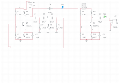
Oscillator is an electronic Circuit which produces sustained oscillations of different frequencies depending upon type of feedback Circuit. At frequencies under 1MHz RC oscillators produce almost perfect sinewave. Above 1MHz LC oscillators are used. In oscillators positive feedback is provided to got undamped or sustained oscillations. In RC oscillators 180 ° phase shift is achieved by three RC network and further 180 ° phase shift is achieved by amplifier circuit. So the feedback signal and input signal remain in same phase and provide positive feedback.
Components Required:-
Resistors, capacitors, transistor, battery, speaker
Circuit Diagram:-
 |
| Fig 1. RC Phase shift Oscillator Circuit |
Working:-
When Supply is given to the circuit only signals in the output are noise signals generated by resistors. These noise signals are amplified and appear at the output terminals. This amplified signal goes to feedback Circuit and goes back in input. To get some sound at the output a small speaker can be connected at output after a amplifier circuit. We can also watch the output in CRO.
Frequency of oscillations can find out by
f = 1/2piRC
f = 1/ 2×3.14×4.7K ohm × 27 nFaraf
f= 1.25 KHz
If we hear this sound it will be a beep sound.
 |
| Fig.2 Output Waveform in simulator |
Author:- Amarjeet Singh Jamwal authored articles on Basic Electronics Engineering, Electric Traction, and Electronics Practical for INFO4EEE Website


Post a Comment