
Deflecting, Controlling and Damping Torques - An essential of Indicating Instruments
Essentials of Indicating Instruments
These are the three torques required for the working of Indicating instruments.
1. Deflecting Torque
The deflecting torque is produced by making use of one of the magnetic, healing, chemical, electrostatic and electromagnetic induction effects of current or voltage and causes the moving system of the instrument to move from its zero position, when the instrument is connected in an electrical circuit to measure electrical quantity.
The deflecting torque may affect due to
- Inertia of moving system
- Controlling torque due to controlling system
- Damping torque due to the damping system
2. Controlling Torque
- It produces force equal and opposite to the deflecting torque so that the pointer deflects to a definite position for a particular magnitude of current (deflection would be indefinite)
- It is used to bring moving system back to its zero position when the causes (I on V) is removed (pointer would not come to a zero when current is removed).
- The controlling torque in indicating instruments is created by spring or gravity.
a. Spring Controls
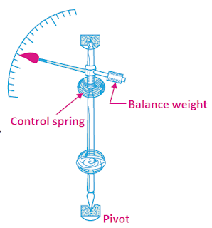 |
| Fig-1 Spring Control |
- The spring should be made of phosphor bronze
- Spring should have non-magnetic in nature.
- Spring should have a small Resistance temp coefficient.
b. Gravity Control
In gravity control, is attached to small weight the moving system and produces controlling torque, when moving system is in deflection position. In zero position, control weight is vertical and when deflected through an angle θ, the control weight would move.
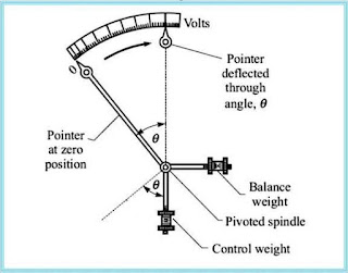 |
| Fig 2 Gravity Control |
Advantage
- Its performance is not time-dependent.
- It is simple and cheap.
- The controlling torque can be varied by adjusting the position of the control weight.
- Its performance is not temperature-dependent.
Disadvantage
- The scale is nonuniform causing problems to record accurate readings.
- The system must be used in vertical position only and must be properly levelled. Otherwise, it may cause serious errors in the measurement.
- As delicate and proper levelling is required, in general, it is not used indicating instruments and portable instruments.
3. Damping Torque
a. Eddy Current Damping
Damping torque in measuring instruments can be produced based on the concept of eddy current flowing in a closed path in which emf is induced based on the principle of electromagnetic indication. A thin disc D of aluminium is mounted on spindle P and moves b/w the magnet, M. and produces emf. in the disc. The emf induced. causes eddy currents which produce damping torque.

Fig 3 Eddy Current Damping
There are three types of damping conditions that show how fast is settled a moving system to its final position as per their relative damping.
1. Critically Damped- When moving systems reaches to its final position smoothly without any oscillations.
2. Under Damped - when the moving system will oscillate to reach its steady state position with decreasing amplitude.
3. Over Damped - When the moving system will reach slowly to its final position.

Fig 4 Deflection state in a moving system
b. Air Damping
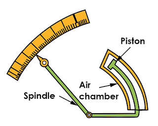 |
| Fig 5 Air Damping |
Author

Rajeev Kumar is dedicated to teaching and research in the field of electrical and electronics engineering. He is always sharing valuable content of the engineering field on this website.


Content is good but there are many spelling mistakes and grammar mistakes
ReplyDelete