LED Chaser Circuit Using BC547
LED Chaser Circuit is an electronic Circuit in which various LEDs blink in such a manner that it looks like each first LED is chasing second one.
Components Required:-
1. Five LEDs (can add as much depending upon the source).
2. Five BC547
3. Ten resistors 56k, 1k or 10k, 220 ohm or 680 ohm, 33k
4. Five Electrolytic Capacitor 10 microfarad 25 V, or 22 microfarad 25 V or 47 microfarad 25 V
5. Bread Board
6. Connecting wires
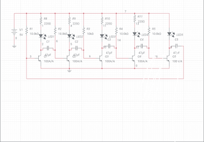
Circuit Diagram:-
 |
| Fig.1 LED Chaser Circuit |
Working:-
In LED Chaser Circuit Transistors switching is done by operating them in saturation and cut off mode. To do this an electrolytic capacitor is placed between collector terminal of first transistor to base terminal of next transistor and so on. Electrolytic Capacitor basically performs duty of providing base signal to transistor by charging and discharging. When the circuit is supplied by 5 Volts battery any one or more transistors starts to act in saturation mode because of base current supplied to transistors through base resistances respectively LED start to glow on switching on the transistors.
Note:- There must be a 220 ohm resistor with each LED to limit LED forward current. While making the circuit keep this in mind because LED may burn. I did not add R12 because of components limitations but while making it practically it is necessary to add 220 ohm resistor. If using 9 Volt Battery then use 680 ohm, 33k or 1k and 56 k combinations of LEDs.As LED normal operation current is 10 to 20 mA.
Author:- Amarjeet Singh Jamwal authored articles on Basic Electronics Engineering, Electric Traction, and Electronics Practical for INFO4EEE Website


Post a Comment