
LED switching using LDR and transistor
LDR:- It is a light dependent resistor which resistance changes with light intensity. In light it exhibits low resistance and in dark it exhibits high resistance. Because of this property LDR is used in automatic switching of lights and motors.
Transistor:- Transistor is a three terminals, three layer semiconductor switching device. For using a transistor as a switch we operate it in cut off and saturation region.
Circuit Diagram:-
 |
| Fig. 1 Transistor working in cut off region |
 |
| Fig. 2 Transistor working in saturation region |
Working :- In this circuit resistor R4 is resistance of a LDR, in Fig.1 there is light so LDR resistance is low say 100 Ω and in Fig. 2 there is dark so LDR resistance is high say 100 KΩ. In first case transistor works in cut off region and very low current (pA)flows through LED so LED does not glow. While in second case transistor work in saturation region and high current (mA) flow through LED so LED starts to glow.
Above image is taken from multisim simulator.
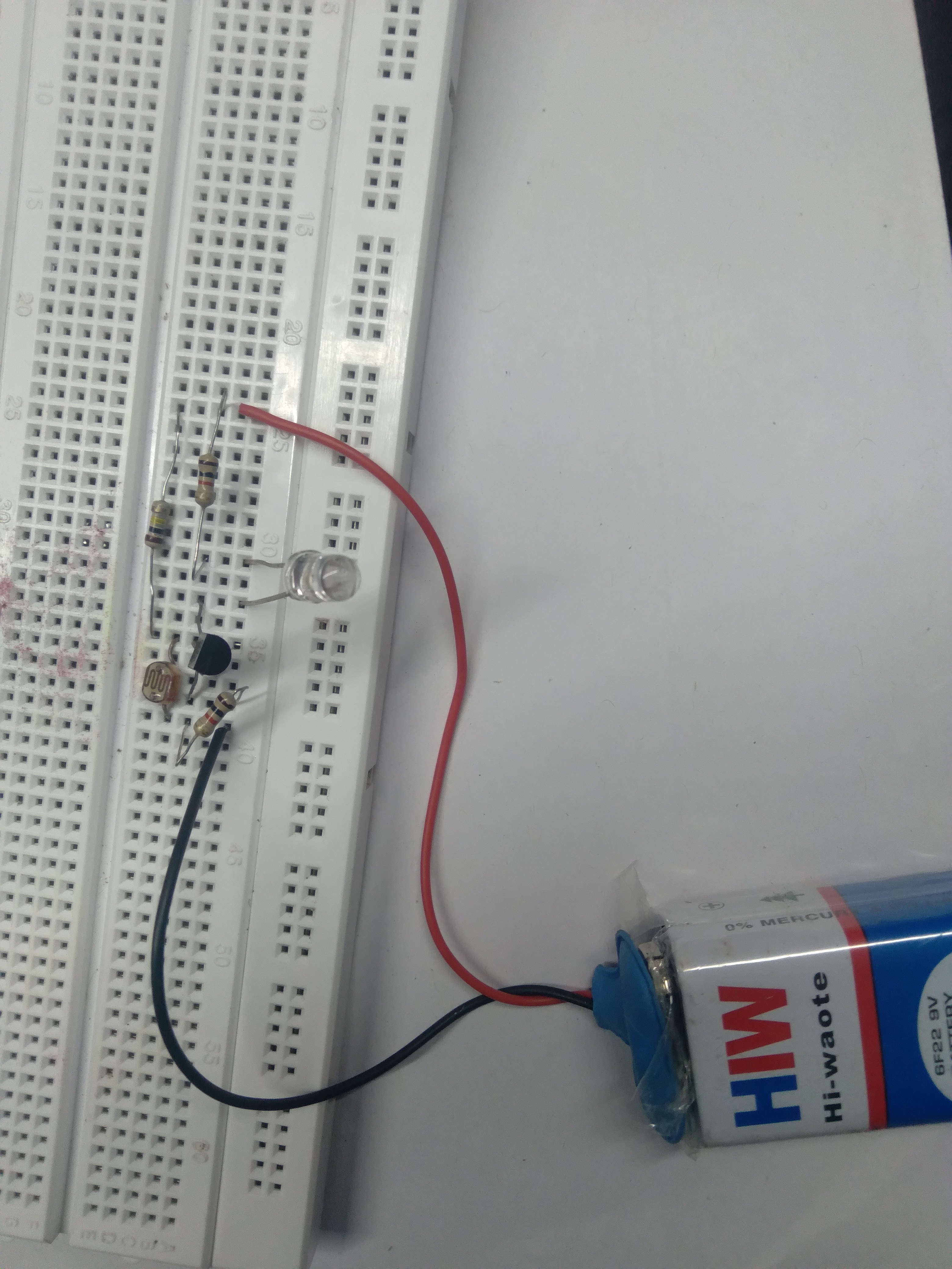 |
| Fig.3 When LDR exposed to light |
 |
| Fig.4 When LDR is placed in dark |
Author:- Amarjeet Singh Jamwal authored articles on Basic Electronics Engineering, Electric Traction, and Electronics Practical for INFO4EEE Website


Post a Comment