Transformerless power supply is used to produce low DC voltage and low current to supply electronics load like LED bulbs, decoration lights,electronics toys etc. It is called a transformerless supply because to reduce 230 V , 50 Hz supply to low voltage, low cuurent AC of same frequency a X rated capacitor/ non polarized capacitor is used in place of a step down transformer.
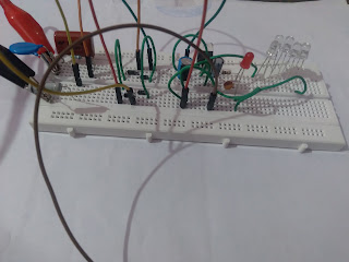 |
| Fig. 1. 12 V, 20 mA Transformerless power supply |
How to choose X-rated or polyster capacitor:-
To find, what value of capacitor will be used voltage divider rule and ohm's law is used. Let the load is of 20 mA and supply voltage is 230 V, 50 Hz AC So to reduce the current a resistance must be inserted in the circuit. The resistance value can be find out by ohm 's law which will be
R= Vpeak/I = (325-12-1.4) V/ 20 mA
= 311.6 V / 20 mA
= 15.580 K ohm = Xc (Capacitive reactance)
In transformerless power supply to produce this resistance/reactance in path a x- rated capacitor of 15580 ohm capacitive reactance will be used. We can find out capacitance and voltage rating in the following way
Xc =1/2pifC
C= 1/2.pi.f.Xc
C = 1/ 2×3.14×50×15580
C = 0.20441 micro Farad
= 204.41 nano Farad
= 204410 pico Farad ~ = 20,0000 n Farad
= 204K, 400V
So in the circuit it will drop around Xc×IL 15580× .02 = 311.6 Volt
As input supply is 230 V, 50 Hz after converting it to peak value it will become 230 V ×1.414 = 325.22 V So to withsatand this voltage 400 V or more rating x-rated capacitor must be used. (It is preferred to use 20 to 30% more voltage rating capacitor).
A bleeder resistance is also connected parallel to x-rated capacitor to discharge the capacitor when circuit is switched off to prevent spark and shock hazard. As this current is of mA rating and micro seconds time, a quarter wattage resistance can be used for this purpose. The value of bleeder resistor can be calculated as written below
R = V^2 / P = 311.6 × 311.6 / 0.25 Watt
R = 388.378 K ohm 1/4 watt
It is preferred to use atleast 470 K ohm 1/4 watt or more value resistor to reduce unwanted power dissipation and slow discharging of X - rated capacitor.
How to choose electrolytic capacitor:-
To find out electrolytic capacitor value following formula is used
C = Q/V
where Q = i.t= 20mA × .01 = .2 mCulomb where t = 1/f = 1/ 100 Hz
V = 2Vm/pi= 2×12/3.14= 7.64 V
C = .2 mCulomb / 7.64 Volt
C = 26.178 uF, 25V or more
So atleast this value of electrolytic capacitor must be used to filter out pulsating DC output of a rectifier. Practically 27 uF or more , 25 or 40/50 V will be used in the circuit. Further with this a ceramic capacitor can also be used to damp out more pulses and get more smooth DC voltage.
How to choose LED resistance value:-
As this is a 12 V DC supply circuit so at the output to have the idea that the output voltage is getting, a coloured LED is used. When a LED glows it takes 15 to 20 mA current and drops 2 to 3 Volt across it, so a resistance must be used to limit the voltage and current to this value. The calculation for this is written below ......
R= (12 V - 2 V) / 15 mA
R = 666.667 ohm
Wattage= I^2 ×R = .015 ×.015 ×666.667
= 0.15 watt
So a quarter watt resistor of this resistance value will be used.
How to select Resistor for current protection:-
When supply is given to the circuit X-rated capacitor acts as short circuit in starting before getting charged and takes 10 to 20 times more current then the load but it happens in micro seconds So to protect the circuit components from this surge current a resistor is used. Generally 1 watt resistor of 22 ohm to 100 ohm is suitable for this purpose because load is of 20 mA so maximum surge current can be upto 200 mA to 400 mA. So when current goes beyond the limit this resistor get burnt and open the circuit to save the component.
Components required:-
1. Polyster Capacitor 204K400V
2. Resistors
3. MOV/Metal Oxide Varistor/Voltage dependent resistor
4. Diode 1N4007
5. Voltage regulator IC / Zenor Diode
6. Electrolytic Capacitor
7. Ceramic Capacitor
8. LED
9. Fuse
Circuit Diagram:-
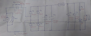 |
| Fig. 2. Transformerless Power Supply schematic diagram |
When 230 V, 50 Hz supply is given to the circuit current get reduced to 20 mA by polyster capacitor C1 reactance Xc. R1 resistor is used as bleeder resistance to discharge polyster capacitor electrostatic charge, when circuit is switched off to provide electric shock and electric spark protection. MOV is used to provide over voltage protection from surges, it get burn and short to save the circuit. Fuse is being used to provide overload and short circuit protection to the circuit or a 1 watt resistance can also be used. This 14 V, 50 Hz supply is rectified by bridge rectifier which produces around 19.796 volt pulsating DC at output. This pulsating DC is further get smoothed by electrolytic capacitor followed by ceramic capacitor and then given to voltage regulator input which produces 12 V DC voltage at output. This voltage is further smoothed by a electrolytic capacitor and ceramic capacitor, where electrolytic capacitor provide controlled voltage and ceramic capacitor provide ripple free voltage at the output. In this way smooth 12 V DC voltage is obtained at output for a 20 mA load.
Note :- Perform practical of this circuit with great care and only if you have technical knowledge & experience of electrical circuits, otherwise you may get electric shock.


Post a Comment