
Step Down Chopper with RL Load

Circuit Diagram
The circuit diagram of step down chopper with RL load is given in Fig. 1. The step down chopper consists of IGBT switch (S) and a diode (D). A dc voltage source of input voltage (VS) is connected at the input while RL (resistor-inductor) load is connected at the output. The switch (S) is operated with signal of 50 % duty cycle.
 |
| Fig. 1 Circuit diagram of step-down chopper with RL load. |
Working
Step-down chopper with RL load operates in two mode.

Mode-1: Switch (S) is ON
The equivalent circuit of step down chopper with RL load during mode-1 is given in Fig. 2. During this mode, high signal (S = 1) is fed to the gate terminal of IGBT switch which turn ON it. A voltage drop of VSW occurs across the IGBT switch. Hence, output voltage (vo) seen across RL load is (VS - VSW). The load current (io) is equal to (i1) which rise from (I1) to (I2).
 |
| Fig. 2 Equivalent circuit diagram of step-down chopper with RL load during Mode-1. |
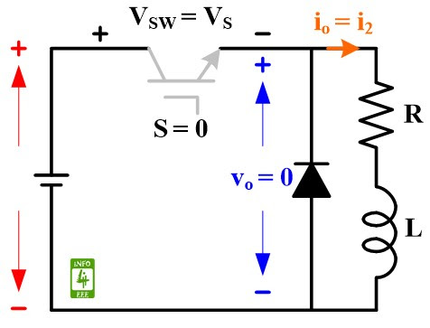
Mode-2: Switch (S) is OFF
The equivalent circuit of step down chopper with RL load during Mode-2 is given in Fig. 3. During this mode, low signal (S = 0) is fed to the gate terminal of IGBT switch which turn OFF it. Full voltage of VS appear across the IGBT switch. Output voltage (vo) across RL load is zero. The load current (io) is equal to (i2) which fall from (I2) to (I1).
 |
| Fig. 3 Equivalent circuit diagram of step-down chopper with RL load during Mode-2. |
The value of I1 and I2 is calculated after solving Equation 1 and 2.
I1 = I2 ✕ e^-{(1-k)✕(TR/L)} . . . (1)
I2 = I1 ✕ e^-(kTR/L) + (VS/R) ✕[1-e^-(kTR/L)] . . . (2)
Waveforms
Waveform showing switching signal (S), input voltage (VS), output voltage (vo), and output current (io) for step down chopper with RL load is given in Fig. 4.
 |
| Fig. 4 Waveforms for step-down chopper with RL load. |
Reference
M. H. Rashid, “Power Electronics: Circuits, Devices and Applications,” Prentice Hall India, Second Edition, 2006.
Author
authored articles on Basics of MATLAB Programming, Power Electronics, Basics of MATLAB Simulink, Basic Electrical Engineering, Power Station, Electromagnetic Field Theory, and many more for INFO4EEE Website.


Post a Comment