We can test resistors, capacitors, inductors, diodes, LED, transistors, and continuity of a circuit with the help of a multimeter.
By color coding and numeric coding of resistor, one can calculate its value. To test a resistor with multimeter, put black probe in common terminal and red probe in Resistor terminal. In Fig. 1, 10 K Ohm resistor is used for testing and knob of multimeter is at 20k.
 |
| Fig. 1 Measuring Resistor using multimeter |
Now connect this resistor across both probes tip to measure resistance. The measured value of resistor with multimeter is 9.83 Kilo ohm. As, this is a 10 Kilo ohm resistor, it has 5 % tolerance. Hence its measured value is 9.83 KΩ.
With a multimeter, One can not find out the value of capacitor but can check whether capacitor is OK or defective. To test a capacitor, connection of multimeter probes will remain same as for resistor but selector switch of multimeter will be set in diode mode (2k) position. Now connect red probe and black probe of multimeter with positive terminal of capacitor and negative terminal of capacitor, respectively. In starting, multimeter will show charging voltage of capacitor up to multimeter battery capacity as shown in Fig. 2. When capacitor is fully charged, multimeter shows 1 on display screen as shown in Fig. 3.
 |
| Fig. 2 Measuring capacitor using multimeter during charging |
 |
| Fig. 3 Measuring capacitor using multimeter when fully charged |
Note:- capacitor acts as short circuit in starting and as open circuit when got fully charged. 3. Testing of diode
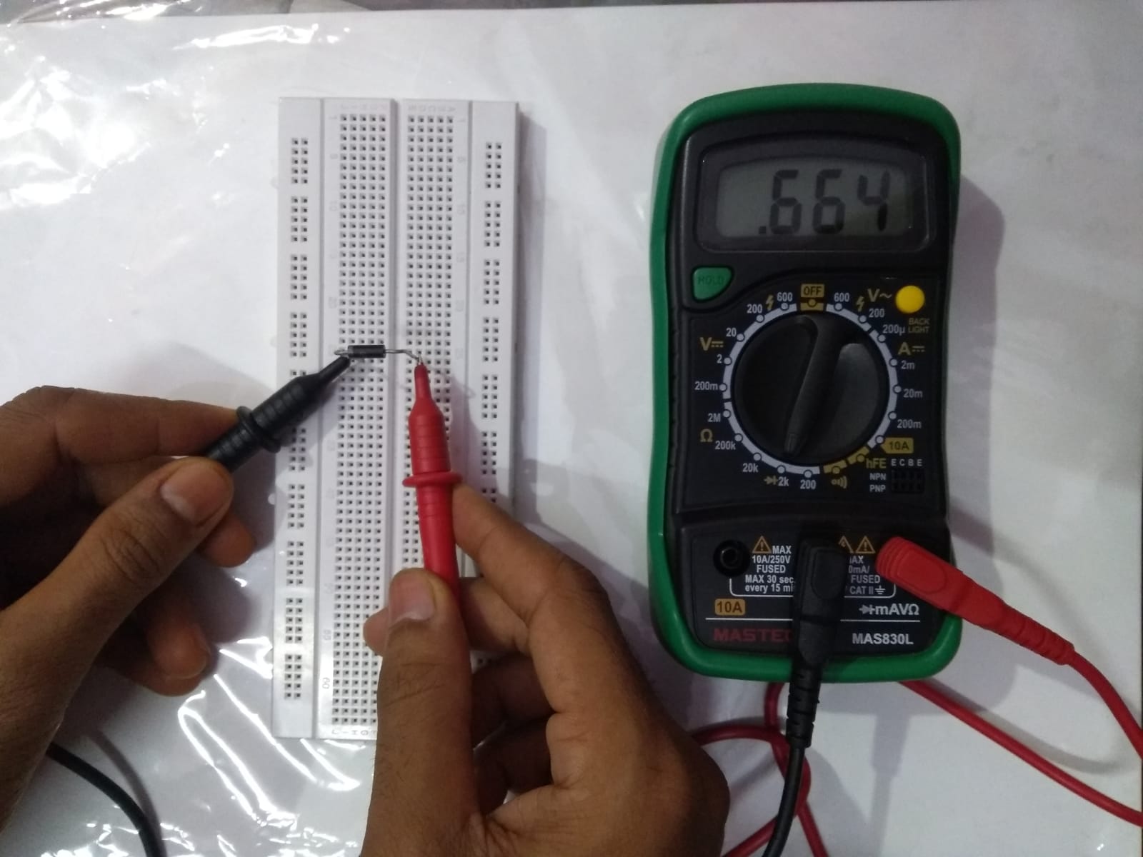
To check the diode, multimeter connection will remain same as for resistor and the selector switch of multimeter will be set on diode (2k) mode. For forward bias mode, connect Red probe and black probe of multimeter with Anode (positive terminal) and Cathode (negative terminal) of diode, respectively. Normally, the voltage drop of silicon diode drops and Germanium diode is 0.7 V and 0.3 V, respectively. As the multimeter is showing 0.664 V as given in Fig. 4, It is a silicon diode. For reverse bias mode, connect red probe and black probe of multimeter with cathode and anode, respectively, multimeter display shows 1 on screen as shown in Fig. 5. If diode shows no voltage drop than it means diode is not OK.
 |
| Fig. 4 Measuring diode using multimeter when forward biased |
 |
| Fig. 5 Measuring diode using multimeter when reverse biased |
 |
| Fig. 6 Measuring transistor using multimeter |
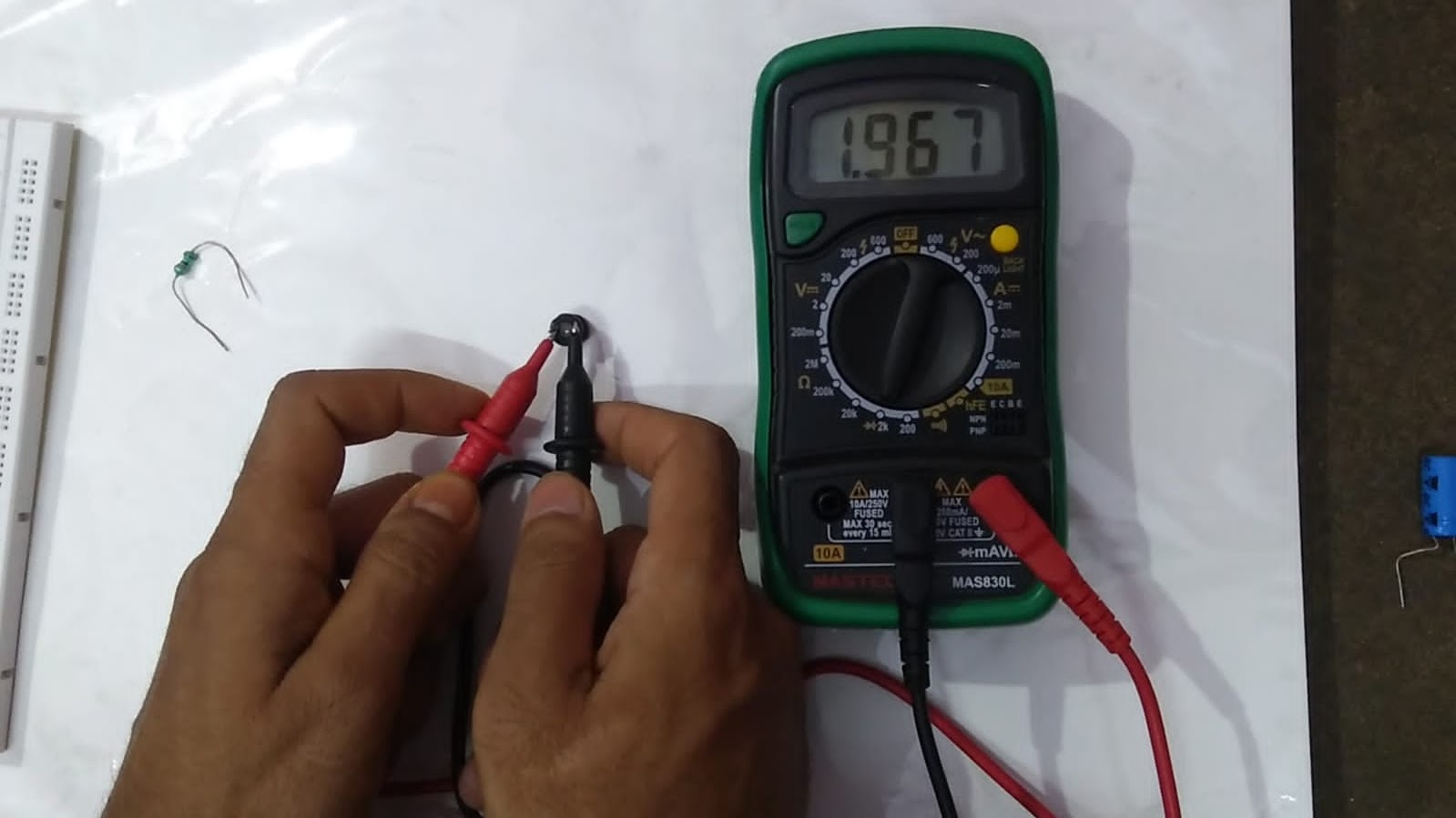
Transistor can also be tested similar to a diode. When, base and emitter of transistor (npn) is connected to red probe and black probe of multimeter respectively, multimeter display shows 0.789 V voltage drop as shown in Fig. 7. When, base and collector of transistor is connected to red probe and black probe of multimeter respectively, multimeter display shows 0.778 V voltage drop as shown in Fig. 8. When, base and emitter of transistor is connected to black probe and red probe of multimeter respectively, multimeter display shows 1 as shown in Fig. 9.
 |
| Fig. 7 Measuring transistor using multimeter as diode |
 |
| Fig. 8 Measuring transistor using multimeter as diode |
 |
| Fig. 9 Measuring transistor using multimeter as diode |
5. Testing of LED
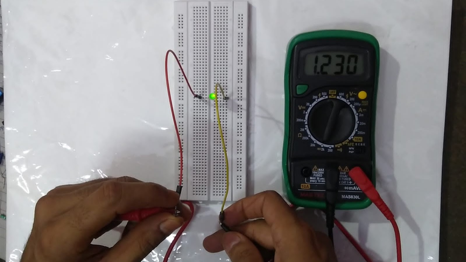
In a LED, longer leg and shorter leg will be anode and cathode, respectively. While inside of LED, cathode end looks more triangular and larger in size where as anode looks like a spike wave and smaller in size. To test LED, connect Red probe and black probe of multimeter with Anode (longer leg) and Cathode (shorter leg) of LED, respectively. If LED starts glowing and multimeter display shows voltage drop (1 to 2 volts), as shown in Fig. 10, then it is OK. If LED does not glow then LED is defective. When red probe and black probe of multimeter is connected with cathode and anode of LED, respectively multimeter display shows 1 as shown in Fig. 11.
 |
| Fig. 10 Testing LED using multimeter when forward biased |
 |
| Fig. 11 Testing LED using multimeter when reverse biased |
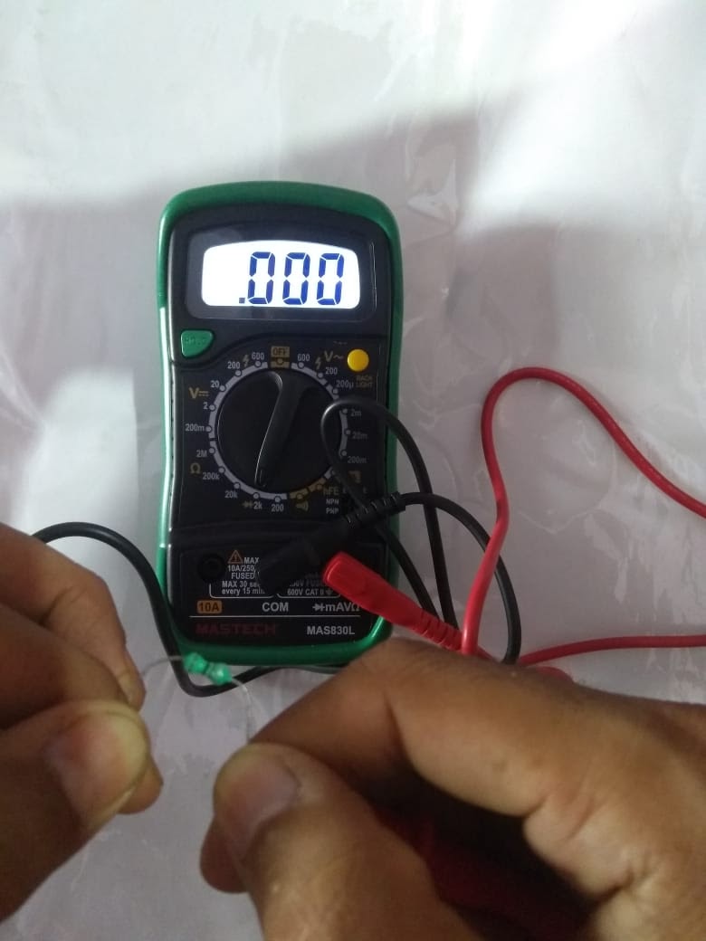
Like capacitors, inductors also stores charge but electromagnetically. In figure one color coded inductor and one normal inductor is tested, in both inductors it also shows charging and discharging but it happens instantly. To test an inductor, connection of multimeter probes will remain same as for resistor but selector switch of multimeter will be set in diode mode (2k) position. Now connect red probe and black probe of multimeter across any one terminal of inductor. In starting multimeter display screen shows charging voltage depending upon multimeter battery capacity as shown in Fig. 12 and Fig. 13. When inductor get fully charged multimeter display screen shows .000 as shown in Fig. 14.
 |
| Fig. 12 Testing of inductor using multimeter |
 |
| Fig. 13 Testing of inductor using multimeter |
 |
| Fig. 14 Testing of inductor using multimeter |
Note:- Inductor acts as open circuit in starting and acts as short circuit when get fully charged.
7. Continuity testing
This test is done to check he tracks of PCB, wiring of equipments and also for checking connections two ends. To check continuity select Speaker like icon by mode selector switch and connect red probe in voltage slot & black probe in common slot. On connecting both probes across any track it will give beep sound if track continuity is OK. Please turn off supply before testing continuity.


Post a Comment