What is Inductor ?
Definition of Inductor
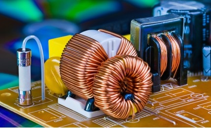
A conducting wire wound in the form of a coil is called an Inductor. When current is passed through it, a magnetic field is formed around the coil and a electromotive force(emf) is generated across two ends of the coil which opposes the change in flow of current through coil.
Thus the current which flows through inductor is controlled by emf or Voltage that is why it is used for current controlling. Formula for emf is
Where - sign indicates that emf opposes change in current
L = Inductance of indicator in Henry
I = Current flowing through inductor
How Inductors Work?
We can understand inductor by a simple hydraulic turbine example in which turbine or water wheel coupled with a heavy fly wheel. Turbine is placed in flowing water and fly wheel is connected with Alternator shaft when water flow then by pressure of water turbine moves which also moves flywheel. In starting due to inertia fly wheel opposes movement and starts moving slowly but when it reached at its full speed and we stop flow of water then it also opposes stopping of movement and reduces speed slowly thus the fly wheel tries to oppose sudden change in speed. To understand inductor we can assume current flow as water flow, inductance as fly wheel inertia and momentum of flywheel as magnetic flux.
Momentum (magnetic flux) =Inertia (Inductance) × water Flow rate (electric current)
The Inertia of an invisible flywheel (Inductor) that tends to keep the same current flowing can be considered as inductance.
As we increase the weight of fly wheel inertia of fly wheel increases similarly as we increase inductor size inductance of inductor increases.
Uses of inductor:-
Where f is frequency of current and L is inductance of inductor in Henry.
3. Inductors are also used in tuned circuit for selection of desired frequency in radio receivers.
Types of Inductor:-
Combination of Inductor:-
1. Series Combination:-
How to find value of Inductor:-
 |
| Fig1. Inductor colour coding chart |
 |
| Fig 2. Inductors tolerance chart |
- For colour coded inductors and numeric coded inductors value of inductance is find out similar to resistors. First two digit written as it is and third one used as multiplier. Last digit or color code tells about tolerance of inductors.
- E,F,G,H,J,K,L,M,V and N are some codes used for tolerance which indicates 0.5%, 1%,2%,3%,5%,10%,15%,20%,25% and 30% respectively.
- Colour coded inductor looks like resistor but the only difference is in its shape. An Inductor diameter is greater at sides in parabolic shape and gradually decreases to end points where as a resistor shape is very much similar to dog bone at its end.


Post a Comment