Complementary commutation is also called voltage commutation, forced commutation, complimentary impulse commutation, or Class-C commutation. It is used in dc choppers and inverters. A thyristor carrying load current is commutated by transferring its load current to another incoming thyristor. i.e. Firing of T1 commutates T2 and firing of T2 commutates T1. A circuit diagram of the complementary commutation technique of thyristor is given in Fig. 1.
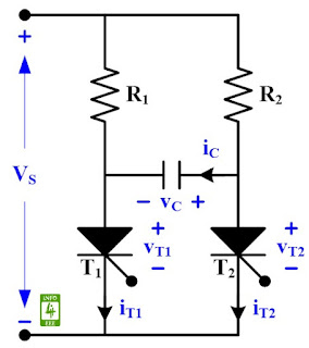 |
Fig. 1 Circuit diagram of complementary commutation.
|
At t = 0, T
1 is turned ON and i
T1 = i
1 + i
C = v ( 1/R
1 + 1/R
2 ). The capacitor is initially uncharged so v
C = 0, i
C(t) = V
S/R
2*e^(-t/R
2C) and v
C(t) = v
T2 = V
S(1-e^(-t/R
2C).
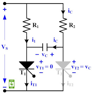 |
| Fig. 2 Circuit diagram of complementary commutation at t = 0. |
At t = t1, T
2 is turned ON, and -v
C is applied across T
1 to turn it OFF. So v
T2 = 0, v
T1 = -V
S, i
C = -2V
S/R
1, and i
T2 = V
S(1/R
1+1/R
2). By KVL, R
1*i
C + 1/C * ∫i
C dt = V
S. Aftter taking Laplace, R
1*I
C(s) + 1/C*[I
C(s)/s - C*V
S/s] = V
S/s. i
C(t) = 2V
S/R
1*e^(-t/R
1C). As i
C(t) flows in opposite direction, i
C(t) = -2V
S/R
1*e^(-t/R
1C). v
C(t) = [1/C*∫i
C dt + V
S] = [1/C*∫(-2V
S/R
1*e^(-t/R
1C + V
S)] = V
S[2e^(-t/R
1C) - 1]. Note: Integration is done from 0 to t.
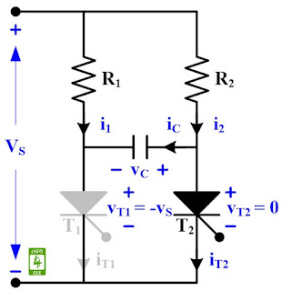 |
| Fig. 3 Circuit diagram of complementary commutation at t = t1. |
At t = t3, T
1 is turned ON, i
T2 = 0, i
T1 = V
S [2/R
2 + 1/R
1), v
T2 = -V
S, v
T1 = 0, i
C = 2*V
S/R
2. V
S applies a sudden reverse bias across T
2 to turn it OFF. v
T1 = 0 = V
S(1-2e^(-t
c1/R
1C). t
c1 = R
1C*ln(2) and t
c2 = R
2C*ln(2). Where t
c1 is circuit turn OFF time for T
1.
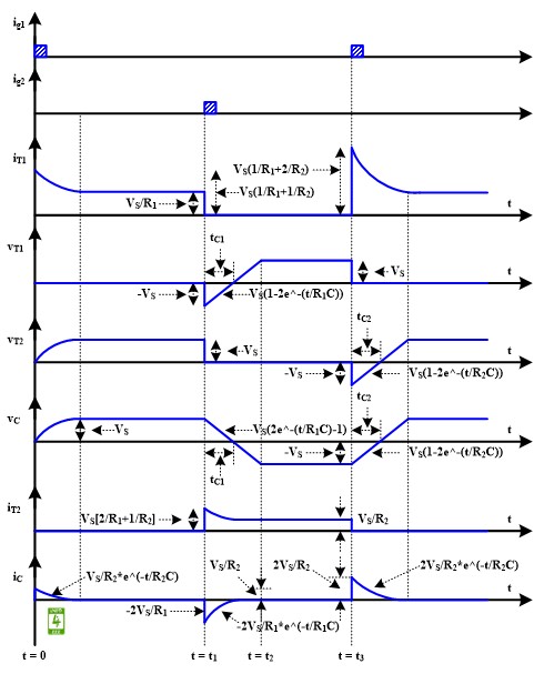 |
Fig. 4 Waveform of complementary commutation
|
Reference
Dr. P. S. Bimbhra, "Power Electronics", Khanna Publishers, Fifth Edition, 2013.
Author
authored 77 articles for INFO4EEE Website since 2012.


Post a Comment