
How To Create Zero Crossing Detector Using MATLAB Simulink
In previous MATLAB Tutorial post, we have discussed about How to draw the Half wave rectifier waveform using MATLAB Simulink. Now in Post-07 of Module-II, we will learn to create the zero crossing detector using matlab simulink.

First of all open new model file and drag some block from simulink library browser into it. Example: Sine Wave under Sources, Hit Crossing under Discontinuities and Scope under sinks. After dragging all above three block into new model, connect them as shown in figure-1.

Figure.1 - Simulink model for zero crossing detector.
Sine wave working as source to generate sine wave which can be seen through first axis of scope. It is also fed to hit crossing which is sensing the zero value in sine wave. whenever zero comes in the sine wave it generates a pulse which can be seen through second axis of scope. The value of sine wave and hit crossing can be updated through its selection panel which can be opened by double clicking on respective block. The selection panel of sine wave block has been shown in figure-2.
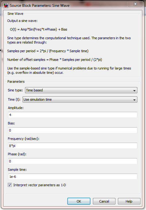
Figure.2 - Sine wave selection panel.
Sine wave block parameters are selected as 4 amplitude, 8*pi radian per second frequency, 0 radian phase and 1 micro second sampling time. The selection panel of hit crossing has been shown in figure-3.

Figure.3 - Hit Crossing selection panel.
Hit crossing block parameters are selected as 0 hit crossing offset and 1 micro second sampling time. The output generated using simulation model given in figure-1 has been shown in figure-4.

Figure.4 - Zero crossing detector output.
It clear from the scope output that the first waveform is of sine wave while the second one is of pulse signal showing the zero crossing in the sine wave.


Post a Comment